Contents
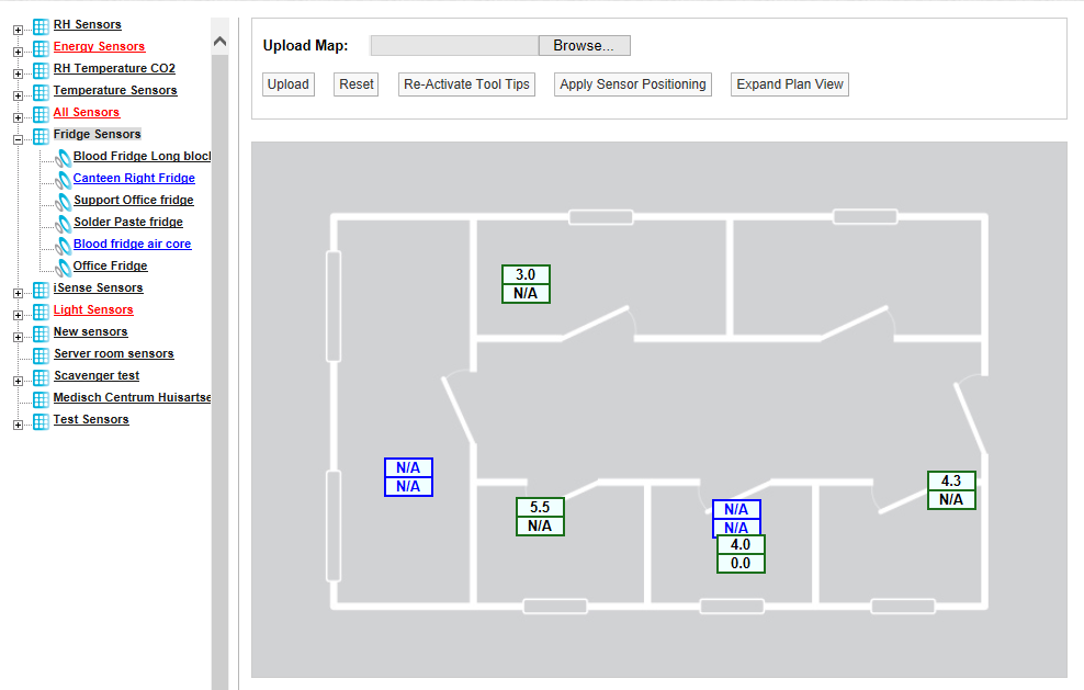
Synergy allows the User to allocate Plans to a Zone. Plan View gives a graphical view of the data.
To Access Plan View
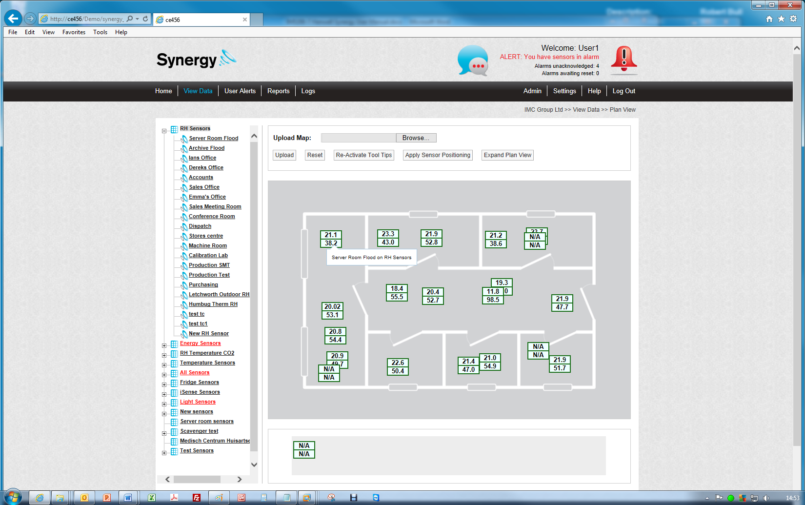
1.Click on the required Zone's name in the left-hand Zone list.
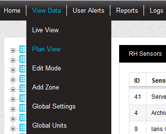
2.Select Plan View from the View Data menu on the top menu bar. See Figure 490 below:
Figure 490
2.Use the Browse function to locate a suitable Plan.
•Suitable Plan formats are .gif, jpg and .png.
•Plan file size should be no larger than 30K.
3.Once a suitable Plan has been located, select Upload to load the image.
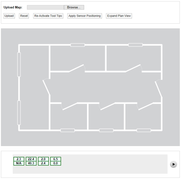
•When a plan is first loaded, all the Sensor icons will be located along the bottom bar. See Figure 491 below:
Figure 491
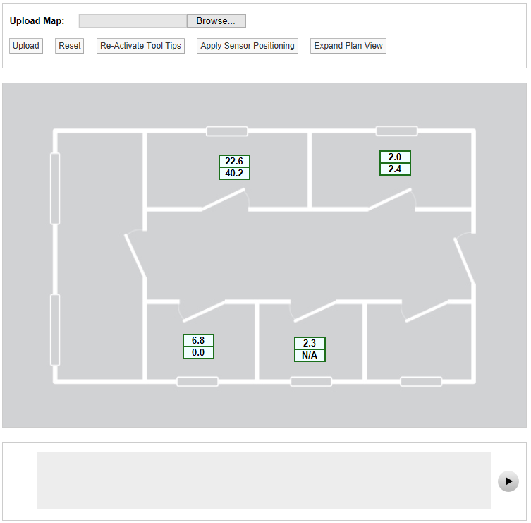
•The icons can be dragged onto the Plan by moving the mouse cursor over the icon, holding down the left mouse key and draging the required sensor icon to the desired location on the Plan. See Figure 492 below.
•Clicking on the arrow to the right of the bottom bar scrolls the list of available Sensors to the left, showing any further available Sensor icons.
•You must have Plan View Edit Permission set to Allowed to be able to do this.
Figure 492
•Each channel is represented by a single block:
•A single-channel device is represented by a single block.
•A double-channel device is represented by two blocks.
•A three-channel device by three blocks.
•See Figure 493 below for examples:
Figure 493
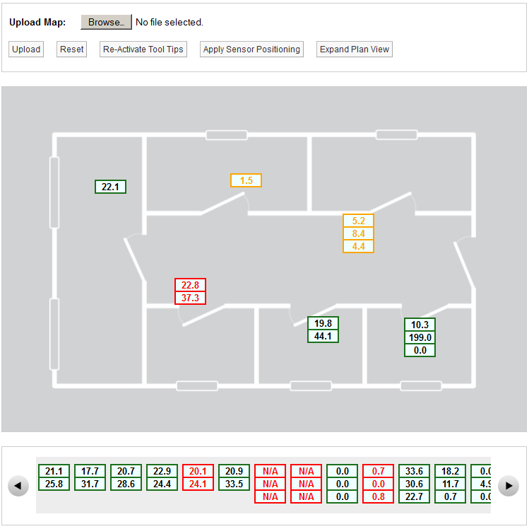
If required all icons can be removed from the Plan and returned to the bottom bar as follows:
1.Click the Reset button.
•A Warning dialog is displayed. See Figure 494 below:
Figure 494
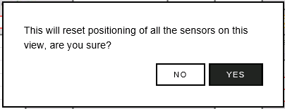
2.To reset all Sensors' positions, click Yes; all icons will be moved to the bottom bar. To cancel the reset, click No.
•Moving the mouse pointer over a Sensor icon displays a tool tip with the sensor name and its parent Zone. See Figure 495.
•Click the Re-Activate Tool Tips button if the tool tips are not visible.
Figure 495
•A larger Plan View can be obtained by clicking on the Expand Plan View button.
•When in the Expanded Plan View, clicking in the Compact Plan View button returns the display to the smaller view.
| Note: | If you reposition sensors in one Plan View, the sensors will remain in their original positions when you switch to a different size Plan View. |
| If you select Apply Sensor Positioning the sensors will move to new positions on the new View. |
•‘Out of Service’ sensors are displayed on the Plan View in blue. See Figure 496.
Figure 496