Contents
Synergy has been designed with the concept of having sensors where the data is input manually.
An example would be data from pest control traps, pests caught in a pheromone traps could be counted on a weekly basis and the numbers entered into a Manual Input Sensor. This data could then be compared against temperature and humidity sensors in the same area to see if there is any correlation in changes in temperature or humidity on insect activity.
•To Add Data to a Manual Input Sensor
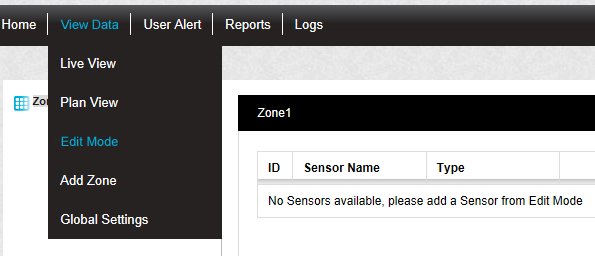
1.Select Edit Mode from the main View Data menu. See Figure 378 below:
Figure 378
•The Sensor and Zone editing/configuration window is displayed. See Figure 379 below:
Figure 379
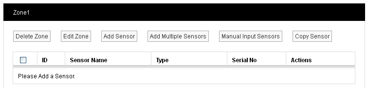
•By default, the Sensor and Zone editing/configuration window for the Zone at the top of the left-hand menu is displayed.
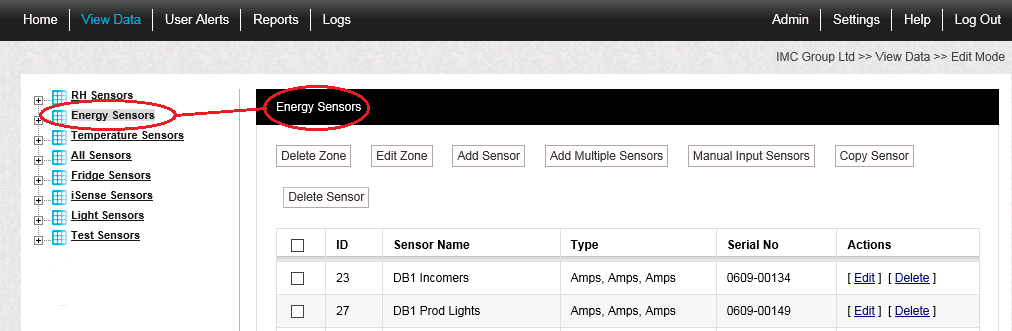
•To display another Zone's Editing and Configuration window, click on the entry for the required Zone in the left-hand menu. For an example, see Figure 380 below:
Figure 380
2.Click on the Add Sensor button to display the Add Sensor window for the selected Zone. See Figure 381 below:
Figure 381
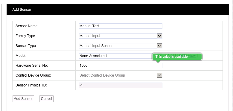
3.Fill out the Sensor Name: field as required.
4.From the Family Type: drop-down list, select Manual Input.
•At this point, the Control Device Group: and Sensor Physical ID: fields are greyed out.
5.From the Sensor Type: drop-down list, select Manual Input Sensor.
6.Add an appropriate Hardware Serial Number into the Hardware Serial No: field.
7.Click on Add Sensor to add the Manual Input Sensor to the selected Zone.
To Add Data to a Manual Input Sensor
1.In the Zone's Editing and Configuration window, click on the Manual Input Sensors button to display the Manual Input Sensors window. See Figure 382 below:
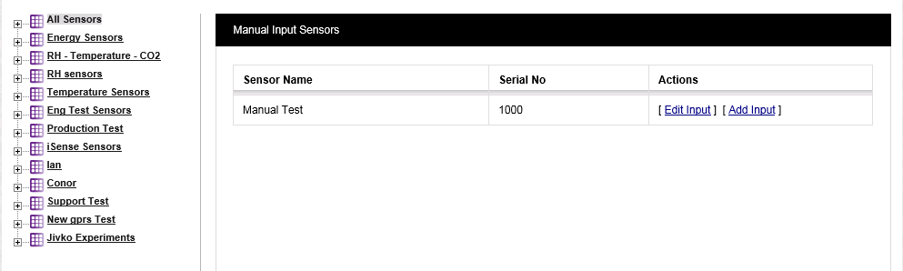
2.Click on [Add Input] to display the Add Input window for the selected Manual Input Sensor. See Figure 383 below:
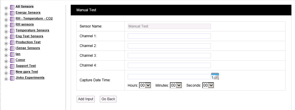
3.Enter the data into the Channel... : fields.
4.In the Capture Date Time: field:
•Either, enter the date manually in the form YYYY-MM-DD or, click on the calendar icon and select the date from the displayed calendar.
•Enter a time, selecting hours, minutes and seconds form the drop-down lists.
5.Click on the Add Input button.
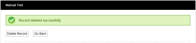
6.The following message will be displayed if the Manual Input has been successfully added:
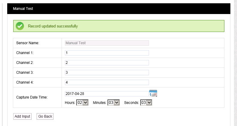
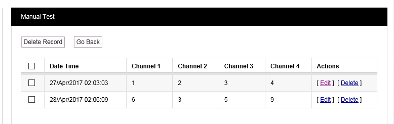
•Clicking on the Go Back button will take you back to a window displaying all of the Manual Input data sets for the sensor. See Figure 384 below:
Figure 384
| Note: | This window is also displayed if you click on [Edit Input] for a selected Manual Input sensor in the Manual Input Sensors window to allow you access to the Manual Input sensor's datasets. |
From this window you can:
•Click on the Go Back button to return to the Manual Input Sensors window from where you can edit input from or add input to the selected Manual Input Sensor
•Edit a Manual Input data set by clicking on [Edit] on the line containing the Manual Input data set to be edited. This takes you to the Add Input window, populated with data set's existing values, from which the data set's details can be edited.
•Delete a Manual Input data set by:
Either:
•Selecting [Delete] on the line corresponding to the Manual Input data set you wish to delete.
Or:
•Checking the box or boxes next to the Manual Input data set(s) you wish to delete.
•Checking the box next to the Date Time column heading to select all of the sensors Manual Input data sets for deletion.
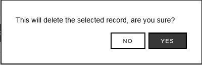
•Clicking on the Delete Record button when you are happy that you are deleting the correct Manual Input data set(s),
Either:
•Clicking Yes on the displayed message window to delete the selected Manual Input data set(s).
Or:
•Clicking No to cancel the deletion.
See Figure 385 below:
Figure 385
| Note: | If you selected Sensors by checking the box(es) next to the ID column heading, a slightly different message window is displayed. See Figure 386 below: |
Figure 386
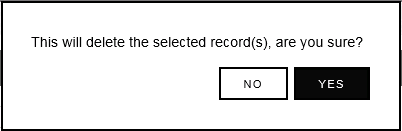
•Clicking on Yes will display the following message. See Figure 387 below:
Figure 387