Navigation:
System Configuration Sensors > Sensors >> Add/Assign Sensors to a Zone
Add/Assign Sensors to a Zone

Contents
Having defined Zones, Sensors can now be added/assigned to them.
•To Add Individual Sensors to a Zone
•To Add Multiple Sensors to a Zone
To Add Individual Sensors to a Zone
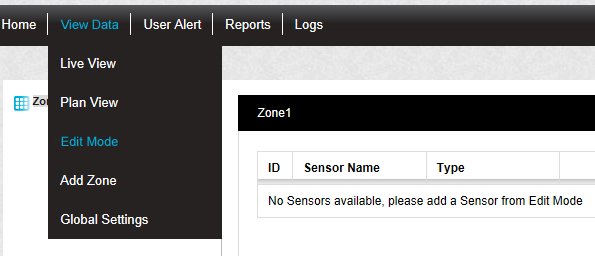
1.Select Edit Mode from the main View Data menu. See Figure 363 below:
Figure 363
•The Zone's Editing and Configuration window is displayed. See Figure 364 below:
Figure 364
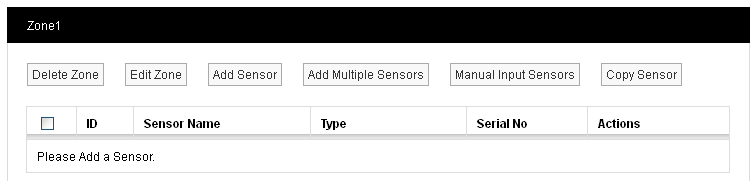
•By default, the Editing and Configuration window for the Zone at the top of the left-hand menu is displayed.
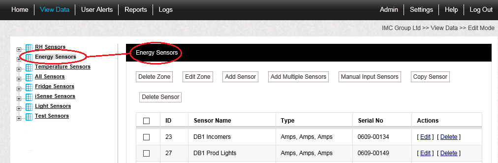
•To display another Zone's Editing and Configuration window, click on the entry for the required Zone in the left-hand menu. For an example, see Figure 365 below:
Figure 365
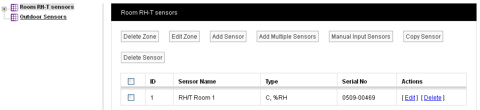
2.Click on the Add Sensor button to display the Add Sensor window for the selected Zone. See Figure 366 below:
Figure 366
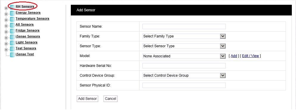
•You will notice, in the example above, that the Zone 'RH Sensors' is highlighted. This is the Zone that the new Sensor will be added to.
•You can sort the order of a Zone's sensor record by clicking the ID heading once or twice to display the Sensor List in ascending or descending ID number order or by clicking the Sensor Name heading once or twice to display the Sensor List in ascending or descending alphabetical Sensor Name order.
3.Fill in the details of the sensor to be added to the selected Zone.
•Sensor Name:
Here you can type a name for the Sensor that means something in relation to either the type of measurement that the Sensor is making or the location, for example, RH/T Room 1 or Room 1.
For this example we are going to call our Sensor, 'RH/T Room 1'.
The ‘family’ for the sensor you are adding.
Select from:
•Hanwell Radio
•iSense
•Manual Input
•Logger
Select the type of Sensor you are adding from the drop down menu.
Descriptions of all of the available Sensor types can be found on our website.
For this example we will add a temperature and humidity sensor, the standard temperature and humidity sensor can be found in the list as Thermistor/RH.
| Note: | To add a Single Channel Linear Sensor, use the standard Dual Channel Linear Sensor hardware, but add it to the system as a Single Channel Linear Sensor. |
This field is not mandatory, you can use the add button to add a list of sensor types or families. This is an aide-mémoire and serves no operational function within the software.
•Sensor Physical ID:
•This is the unique sensor ID, it can be in the range 1 to 255.
•For this example we are going to select sensor 1.
•If the Physical ID is already used by another sensor, the system will suggest the next available ID.
This is the transmitter serial number and can be found on the back of the transmitter, you can either enter the serial number in the dialog box in the following format, 0113-00001 or you can enter a 0 (zero), if a 0 (zero) is entered the serial number will be filled in automatically by the Synergy Management Application when the sensor is synchronised. For details see Document Number: IM5210 Synergy Management Tool manual.
•The Control Device Group is the wireless receiving device that will receive the data from the transmitters.
•The Control Device Group is selected from the drop down menu.
•Select the Control Device Group which corresponds to the Site and is compatible with the wireless transmitters used at that Site.
•For more details see the Adding Devices section.
•For this example, we are going to select IMC.
4.Once you are happy with the details click on the Add Sensor button to add the Sensor to the Zone.
•Click on the Cancel button to cancel adding the Sensor to the Zone.
•The new sensor will now be displayed in the list on the right hand side of the screen along with any other sensors associated with the Zone.
•A '+' symbol to the left of the Zone's icon in the left-hand menu shows that there are sensors associated with that Zone.
•Clicking on the '+' symbol allows access to sensor properties for the selected Zone to enable the sensors to be configured. See Accessing Sensor Properties.
See Figure 367 below:
Figure 367
•Further sensors can be added by repeating the steps from paragraph 2 onwards.
•When adding more sensors, additional Zones can also be added and additional sensors added to those Zones.
•Associating a Sensor with a CR2 GPRS Device.
| Note: | iSense sensors are handled as a special sensor in Synergy. |
•They are not part of a Control Device Group and have a special PID value of zero.
•Synergy collects iSense data by making an outgoing TCP/IP connection to the IMC Remote Data Service.
As this connection is made to the standard HTTP Port (8081) on the IMC Remote Data Service, the System operates in the vast majority of cases with no need to make Network or Firewall configuration changes.
To edit a Zone's existing sensors:
1.Select [Edit] in the line corresponding to the sensor to be Edited in the Zone's Editing and Configuration window to display the Edit Sensor window. See Figure 368 below:
Figure 368
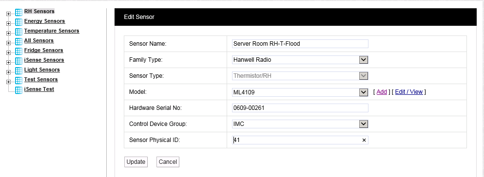
2.Edit the displayed details as required.
3.Click on the Update button.
•The sensor's details are updated and you are returned to the Zone's Sensor and Zone editing/configuration window.
To Add Multiple Sensors to a Zone
Multiple sensors of same Family Type, Sensor Type and Model and with the same Control Device can be added to a Zone as a batch.
1.Click on the Add Multiple Sensors button in the Zone's Editing and Configuration window to display the Add Multiple Sensor window. See Figure 369 below:
Figure 369
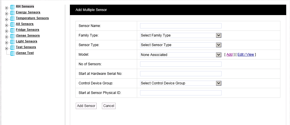
2.Fill in or select the required sensors' details from the dialog boxes and drop down lists in the window:
•Sensor Name:
The name to be allocated to all of the added sensors.
•No of Sensors:
The number of sensors you want to add in the batch.
•Start at Hardware Serial No:
The individual sensor's Serial Numbers in the batch will be numbered sequentially from the value you enter here.
•Start at Sensor Physical ID:
The individual sensor's Physical IDs in the batch will be numbered sequentially from the value you enter here.
3.Click on Add Sensor to add the batch of sensors.