Navigation:
System Configuration Sensors > Configuring Sensors > Calibration - General >> Calibration - Using the Management Tools
Calibration - Using the Management Tools

Contents
Calibration involves checking the values recorded by a Sensor against values known to be correct (the Reference Values) and confirming that the two are equal.
If necessary, a Sensor's Calibration Settings are then adjusted to ensure that it's displayed and transmitted values accurately correspond to these Reference Values.
•Other terms for Reference Values are Applied Values or Calibration Points.
Sensors can be calibrated on-site by the Client or IMC personnel by using the following procedure.
| Note: | This procedure assumes that the Synergy Management Tool or Synergy Remote Management Tool has been installed and that suitable calibration equipment (for example a Humidity Generator or Dry Block Temperature Generator) is available. |
Opening the Management Tool
As well as Synergy, Calibration requires the use of -
Either:
The Synergy Management Tool.
Or:
The Synergy Remote Management Tool.
Opening the Synergy Management Tool
1.Open the Synergy Management Tool by -
Either:
Clicking on the Desktop Icon:

Or:
Selecting it's entry in the Start menu.
Opening the Synergy Remote Management Tool
1.Open the Synergy Remote Management Tool by -
Either:
Clicking on the Desktop Icon:
Or:
Selecting it's entry in the Start menu.
•The SYNERGY Connection window is displayed. See Figure 411 below:
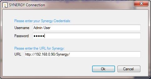
Figure 411
2.Enter a Username and Password and the URL of the synergy system that you wish to communicate with.
•The URL will be in the form: http://<hostname>/Synergy/, replace <hostname> with the Hostname or IP address used to reach your Synergy server.
3.Ensure that the fields' entries are correct and click OK to continue.
Selecting the Sensors to Calibrate
The SYNERGY Management window is displayed once the selected Management Tool has loaded. See Figure 412 below:
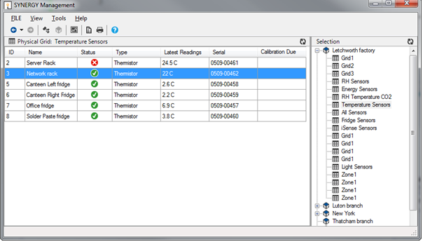
Figure 412
•Sensors can be browsed to by navigating Sites and Groups.
To switch the view mode between Sites and Groups,
Either:
Select the corresponding View menu option.
Or:
Click on the appropriate tool bar button.
•Sites and groups can be navigated by; using the tree view to the right of the screen, using the Next Grid and Last Grid options in the View menu or using the Back and Forward tool buttons in the top left of the screen. See Figure 412 above.
•Sensors are selected by simply clicking on their icons.
The Synchronise process takes data from a connected USB device and updates its Serial Number and Calibration details in Synergy at the same time as setting the Physical Transmit ID of the device.
•Synchronising Sensors facilitates efficient communication between the Sensor and Synergy.
•Even if the sensor is already running on Synergy, it is strongly recommended to carry out Synchronisation to set a faster transmit rate for the Calibration run.
To Synchronise a Sensor:
1.Ensure that the Sensor is plugged in using a USB cable.
2.Select the correct Sensor using the Synergy Management Tool. See Figure 412 above.
3.Right click on the selected Sensor and select Sync Selected Sensor from the displayed menu.
•The Synergy Synchronise USB Sensor Vx.x window is displayed. See Figure 413 below:
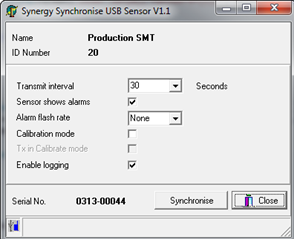
Figure 413
| Note: | The sensor selected must match the physical device or the program will not complete. |
4.Make a note of the value in the Transmit interval field, so that the unit can be reset after calibration.
5.Select the required TX interval from the Transmit interval drop-down list (60 seconds is recommended for Calibration).
•The Synchronise window completes loading and all the fields are populated.
6.Click the Synchronise button and follow the instructions given until it reports that the Synchronisation is complete.
7.Close the window to finish and update the Synergy database.
8.Repeat this procedure for all Sensors.
Selecting Reference Values
•The chosen Reference Values should be equally spaced within the published temperature range of the Sensor/Transmitter, but can take account of the actual range of temperatures that the particular Sensor/Transmitter will be subject to.
•A minimum of three Reference Values should be chosen to calibrate a Sensor - High, Medium and Low within the required value range.
•It is not advisable to calibrate over a very small range. For example, if a unit was being used at in an environment at +5°C and had calibration points of, say, 0, +5 and +10°C applied, if the unit was then moved to an environment at +30°C the calibration would be invalid.
However, if the unit was always going to be used in an environment with a temperature range between 0°C and +10°C and readings outside this range were unimportant, then it would be fine to calibrate over the narrower range.
Recording Reference Values
1.Set up the Sensors/Transmitters to be calibrated and an appropriate Reference Probe in suitable calibration equipment (for example a Humidity Generator or Dry Block Temperature Generator).
2.Set the calibration equipment to the required Reference Value and leave it to stabilise i.e. give a consistent reading at this value.
•As this value is set by the Client/IMC it can also be known as the Applied Value.
3.Make a note of the reading from the Reference Probe and the time it was taken.
•This is the Reference Value i.e. the value which the Sensor should record and will be adjusted to match if not.
Recording As Found Calibration Data
1.Double click on the entry for the Sensor being calibrated in Synergy.
2.Zoom in on the graph to get a reading from the same time the Reference Value's reading was taken.
•This reading will be your As Found reading ie. the value that the Sensor 'sees' at, for example, the actual temperature/humidity represented by the Reference Value generated by the calibration equipment and measured by the Reference Probe.
3.Make a note of the As Found reading.
Recording Raw Calibration Data
1.Check the Reference Value's reading again. This should not have drifted.
2.Using the Synergy Management Tool, check the that the latest readings (listed in the Latest Readings column of the Synergy Management window) for the Sensor being calibrated are the same as the As Found readings displayed in Synergy noted above. See Figure 414 below:
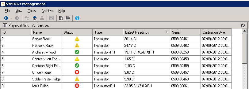
Figure 414
3.Put the Management Tool into CAL mode (View > Calibration Mode).
•The Latest Readings column will have changed to Latest Calibration and changed colour to orange. See Figure 415 below:
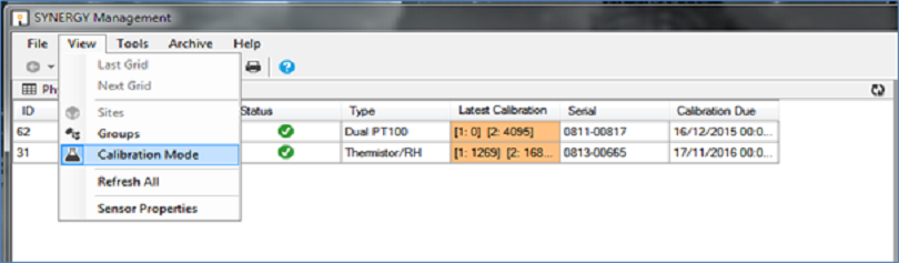
Figure 415
4.Note down the the Raw Numbers generated by the Sensor from the Latest Calibration column.
•These represent the Raw Numbers generated by the Sensor at the selected Reference Value.
| Note: | For Dual Sensors, two values [1. ] and [2. ] will be given; Temperature being represented by Channel 1. and Humidity by Channel 2. Not all Sensors/Transmitters have two channels, some have one and others have three. |
5.Repeat steps:
•Recording Reference Values
•Recording As Found Calibration Data
and
•Recording Raw Calibration Data
for the remaining selected Reference Values.
If the As Found values are the same as the Reference Values, the Sensor is accurately measuring the actual values and no adjustments are required. In this case, go to Resetting TX Interval below.
If the As Found values are not the same as the Reference Values, you will need to adjust the Sensor's Calibration Settings. See Editing a Sensor's Calibration Settings below:
Editing a Sensor's Calibration Settings
In Synergy:
1.Access the Calibration icon in the left-hand menu of the Editing and Configuration window as outlined in Accessing Sensor Properties.
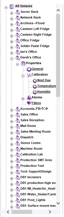
2.Click on the + sign next to the Calibration icon to expand the Calibration property entries. See Figure 416 below:
Figure 416
3.Click on the icon(s) representing the parameter(s) the Sensor is measuring, in this example the Temperature or Humidity icon, to display the parameter's window, in this case, the Temperature or Humidity window, for the selected Sensor/Transmitter. See Figures 417 and 418 below:
Figure 417
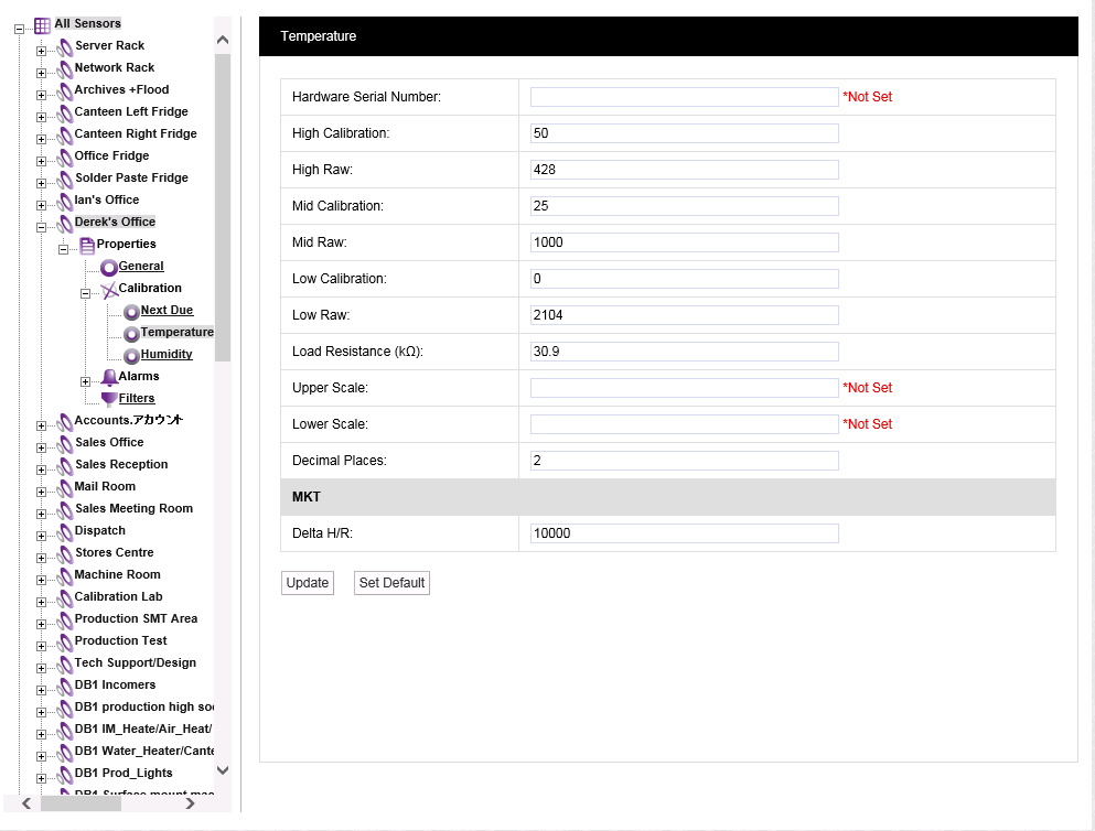
Figure 418
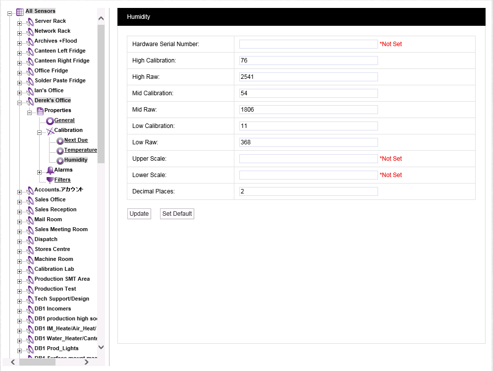
3.Enter the selected High, Mid and Low Reference Values into the High Calibration:, Mid Calibration: and Low Calibration: Fields.
4.Enter the Raw Numbers from the As Found readings into the High Raw:, Mid Raw: and Low Raw: field for the corresponding High, Mid and Low Reference Values.
•This will 'tell' Synergy that these Raw Numbers represent the specific Reference Value rather than the incorrect values originally generated by the Sensor from the Raw Numbers.
5.Select Update to confirm the details and apply the Calibration adjustment.
•If the Update has been successful, the following message will be displayed. See 419 below:
Figure 419

6.Repeat for all Sensors.
Sending Calibration Values to Units
This Calibration process takes Sensor Calibration settings, either existing or recently adjusted, from the Synergy database and loads them into a selected Sensor.
To send Calibration values to a Sensor:
1.Ensure that the Sensor is plugged in using a USB cable.
2.Select the Sensor from the Synergy Management Tool's SYNERGY Management window and right-click on its entry in the table.
3.Select Calibrate Selected Sensor from the displayed menu.
•The Synergy USB Sensor Calibration Vx.x window is displayed and its fields are populated. See 420 below:
Figure 420
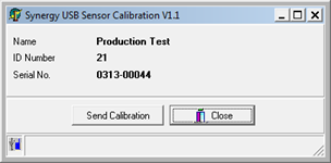
| Note: | The Sensor's Serial Number and Type must match or the program will not complete. |
4.Click on the Send Calibration button and follow the instructions given until it reports that the calibration is complete.
5.The Sensor's display should show the same value as displayed in Synergy.
6.Repeat steps 1 - 5 for all units.
Recording 'As Left' Calibration Data
Before completing the Calibration, check Sensor As Found readings at all Reference Values.
•The readings should be close to the Reference Values taking into account the margins of error of the equipment/process being used.
•Note down the As Left readings on the worksheet.
•The readings shown on the Sensor's display and in Synergy should match if the above process has been carried out correctly.
Resetting TX Interval
Using the Synchronise process in the Synergy Management Tool, reset the TX interval for each unit to its original interval recorded earlier.
Repeat for all units.
Calibration Certificate
If a Calibration Certificate is required, use the use the data above to fill out its details ie:
High, Low and Medium Raw Numbers/Counts
High, Low and Medium Reference Values
High, Low and Medium As Found Values